Posts

Showing posts from May 24, 2009

Using your Real PC in GNS3

Image
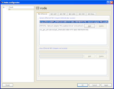
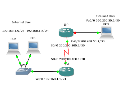
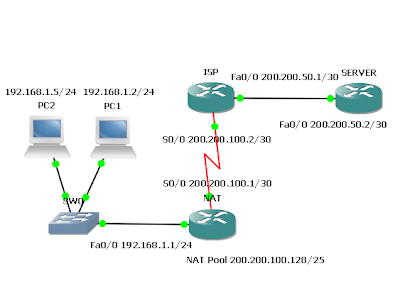
One of the interesting things about GNS3 and Dynamips is that you can connect your topology to the real world. For some of your CCNA and CCNP studies you may need to run an actual Web browser or Cisco’s Security Device Manager (SDM) among others. Just connect your topology to your real PC. You could even connect to virtual machines running on your computer inside VMware or Virtual PC. I’ve even set up two copies of Windows XP Professional running inside VMware virtual machines. Then I ran Cisco soft IP Phones that could talk to themselves. You could connect your virtual network to a real network as well. Connecting a virtual topology running within GNS3 and Dynamips to real devices is very exciting, but again, your throughput is going to be limited compared to using real equipment for the entire topology. It only makes sense to use GNS3 and Dynamips in a lab environment and for learning purposes. Any other usage is highly discouraged! Connecting your topology to your real PC is very si

Using a Router that acts Like a PC

You may also simply add another router to your topology and configure it to act like a PC. This method would use more memory and processor cycles than the previous method, so I would only recommend this method as a secondary choice. Just add a router and enter the following commands: Router(config)# no ip routing (Turns off IP routing function ) Router(config)# interface fa0/0 (Switches to FastEthernet interface) Router(config-if)# ip address address subnet_mask (Assigns IP address and subnet mask to interface ) Router(config-if)# no shutdown (Turns interface on ) Router(config-if)# exit (Returns to global configuration mode ) Router(config)# ip default-gateway (gateway_address Configures the default gateway ) Router(config)# ip http server (Optional – starts http server process Connect the router (acting as a PC) to the rest of your topology.)

How to Add Virtual PC to your GNS3 Topology

Image
The Virtual PC Simulator is a program that runs within Windows or Linux. It has limited functionality, but most important, it allows pings and traceroutes. These are the most common testing commands used during CCNA or CCNP training and are often the only commands needed. Using VPCS you will save memory and CPU cycles. If you do not need more functionality in a workstation within your topology, I highly recommend VPCS. The Virtual PC Simulator is a free product available at the following. Web site: http://wiki.freecode.com.cn/doku.php?id=wiki:vpcs How to install in windows? Download the software here and extract to your folder. You will find file cygwin1.dll in the extracted folder. Go to C:\Program Files\GNS3\Dynamips , search and rename the file cygwin1.dll into cygwin1.dll.old and copy the file cygwin1.dll from your vpcs folder to this folder. Open command prompt, enter the vpcs folder and type vpcs.exe. It is best to open the Virtual PC Simulator before starting GNS3. Welcome to

Routing between RIP v1 and RIP v2

Image
Routers Used : 3640 w/ NM-4T and NM-1FE-TX modules IOS : c3640-jk9s-mz.124-16a Objective In this lab, configure RIP v1 and RIP v2 routing protocols. RIP v2 will be configured to accept RIP v1 updates. Scenario RIP v1 is presently running between Jakarta, Tegal, and Surabaya. New routers that support RIP v2 and variable-length subnet mask (VLSM) have been installed at the Tegal and Surabaya headquarters. However, an upgrade of the Jakarta router, which presently does not support RIP v2 will be installed at a later time. RIP v2 will have to be configured between Tegal and Surabaya. Surabaya will then need to be configured to receive RIP v1 updates so the Jakarta router will be able to communicate with Tegal. Step 1 Build the network according to the diagram and configure all routers with RIP v1. Test connectivity between the routers and troubleshoot as necessary. A ping should be successful from one end of the network to the other. Step 2 Verify that RIP v1 is running. There are several

Subnet Calculator

Don't be confused to calculate subnet of your IP Address. Please download and try this tool from Boson. Also useful to check wildcard Mask. It displays Host IP address, mask bits, the class of address, range of addresses for that class and the binary representation of that address.

Configuring IGRP

Image
Routers Used: 2621 w/ CISCO2600-MB-2FE and WIC-2T modules IOS: c2600-i-mz.121-5.T9 Objective In this lab, configure IGRP for unequal cost load balancing and tune IGRP timers to improve performance. Scenario International Travel Agency (ITA) has asked for IGRP to be implemented in its WAN. Step 1 Build and configure the network according to the diagram. If the configuration files are used from the previous lab, remove all routing protocols. Note : PC1 and PC2 are not required to complete this lab, but they might be used in testing or as Telnet clients. If used, the PC1 gateway may be either Dion1 router or the Dion2 router. On all three routers, configure IGRP for Autonomous System 24, and enable updates on all active interfaces with the network command. Arief(config)#router igrp 24 Arief(config)#network 192.168.1.0 Arief(config)#network 192.168.2.0 Arief(config)#network 192.168.3.0 Dion1(config)#router igrp 24 Dion1(config)#network 192.168.1.0 Dion1(config)#network 10.0.0.0 Dion2(con

Migrating from RIP to EIGRP

Image
Routers Used : 3640 w/ NM-4T and NM-1FE-TX modules IOS : c3640-jk9s-mz.124-16a Objective In this lab, configure RIP v2 and then EIGRP so that their metric calculations can be compared. Scenario International Travel Agency (ITA) currently uses RIP v2 as its interior gateway protocol. Migrate its network to EIGRP. Step 1 Build and configure the network according to the diagram. Note: PC1 and PC2 are not required to complete this lab, but they might be used in testing or as Telnet clients. If used, the PC1 gateway may be either Dion1 router or the Dion2 router. On all three routers, configure RIP v2 and enable updates on all active interfaces with the network command: Dion1(config)#router rip Dion1(config-router)#version 2 Dion1(config-router)#network 192.168.1.0 Dion1(config-router)#network 10.0.0.0 Dion2(config)#router rip Dion2(config-router)#version 2 Dion2(config-router)#network 192.168.2.0 Dion2(config-router)#network 10.0.0.0 Arief(config)#router rip Arief(config-router)#version 2

Network Address Translation – Port Address Translation and Port Forwarding

Image
Routers Used: 2621 w/ CISCO2600-MB-2FE and WIC-2T modules IOS: c2600-i-mz.121-5.T9 Objective In this lab, Port Address Translation (PAT) and port forwarding are configured. Scenario The International Travel Agency is planning to launch an informational Web site on a local Webserver for the general public. However, the one Class C address that has been allocated will not be sufficient for the users and devices the company has on this network. Therefore, a network is configured that will allow all internal company users access to the Internet and all Internet users access to the company’s informational Web server through static NAT and PAT. Internal user addresses must be translated to one legal global address and all Internet Users must access the informational Web server through the one legal global address as well. Step 1 Build and configure the network according to the diagram. If you are using the configuration files from the previous lab, remove the NAT pool (public) and the stati

Network Address Translation – Static NAT and Dynamic NAT

Image
Routers Used: 2621 w/ CISCO2600-MB-2FE and WIC-2T modules IOS: c2600-i-mz.121-5.T9 Objective In this lab, static Network Address Translation (NAT) and dynamic NAT are configured. Scenario The International Travel Agency needs approximately 100 private IP addresses translated in a oneto-one fashion with a pool of public IP addresses. To do this, ITA will use NAT translation with a portion of its class C address space allocated by ISP. Step 1 Build and configure the network according to the diagram. Use ping to test connectivity between the NAT and ISP routers, between the workstations and the default gateway, and between SERVER and ISP. Step 2 Since no routing protocol will be enabled, configure a default route to the Internet on the NAT router: NAT(config)#ip route 0.0.0.0 0.0.0.0 200.200.100.2 ISP needs to be able to reach hosts on the 192.168.0/24 network. But these hosts will have their IP addresses translated to public IP addresses in the 200.200.100.128/25 network, so a static ro